The landscape of dentistry, particularly implant dentistry, is rapidly changing. More and more patients are finding themselves at the crossroads presented by failing dentition. The options available are often limited to full arch rehabilitation with implants vs progression to partial or full edentulism.
The ‘All-On-X’ concept has been around for many years and in that time as a profession we have come to learn the importance of elements such as detailed planning from a restoratively led perspective, restorative materials and their limitations, position of implants and their anterior-posterior spread, the need for a variety of abutment types, implant design etc., the list is endless.
We have also taken steps to meet the demands of patients to reduce the number of appointments, for shorter visits, the quality of the end result, long term predictability and customer service. This has meant that as a profession we have had to continue to develop the efficiencies of our procedures and utilize digital workflows to complement a clinical skillset in order to streamline full arch rehabilitation in the failing dentition with increased precision, predictability and patient-centered outcomes.
The use of guided surgery in the placement and immediate loading of four to six implants represents a predictable treatment option for the edentulous patient (Tallarico et al. 2016).
The case report below outlines the various key stages of a digitally planned, fully guided dual arch immediate load case, using metal stackable guides. The final prostheses were planned for FP3 designs. An FP3 design is a fixed prosthesis which replaces the missing teeth as well as the hard and soft tissue component of the edentulous site. It is often used when there is an extended period of bone loss or when space is required for adequate prosthesis thickness or to hide the transition zone patient in full smile (Misch 1989).
Initial presentation
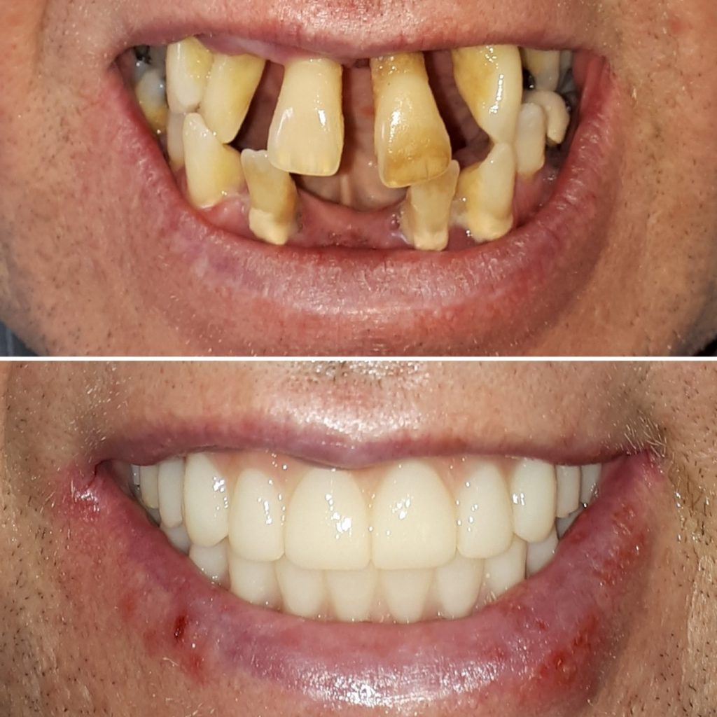
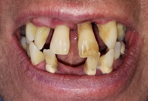
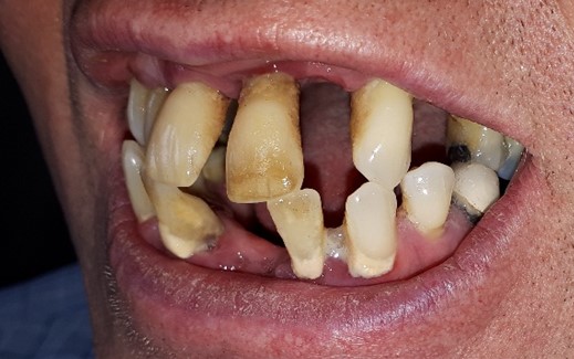
A 54-year-old man with several missing and compromised teeth in both the maxilla and mandible presented for full mouth rehabilitation treatment. His primary concerns were functionality and appearance. He was very self-conscious about his smile and had been lacking in confidence for many years.
Following extensive clinical and radiographic examination, it was determined that the remaining dentition in both the maxilla and mandible were terminal. A thorough discussion on the options available took place. The patient wished to proceed with IFAL (immediate full arch load) on both arches as this would meet all his treatment goals for improved functionality, appearance, and self-confidence. His medical and social history were clear of any contraindications.
Record taking
For accurate planning and predictable treatment outcomes, several pre-treatment records were taken (Fig. 1).
Photographs – Full face, full smile photo, plus profile photo if Class II or III. Retracted photographs front, left side, right side IN occlusion.
Maxillary & mandibular master casts or impressions – Upper and lower alginate impressions, with and without partial dentures were taken. These were immediately digitized to limit any loss of accuracy.
Bite registration – Centric occlusion bite using blue mousse.
CBCT record – Two separate scans were taken – one of each arch using the bite fork to keep the dentition open and out of occlusion. A tip to improve image quality in the buccal corridors is to place a cotton roll between the teeth and mucosa.
Shade – Vita shade A2 was chosen by the patient.

The above information was then used in conjunction with the lab to firstly design the prosthesis. This is the basis from which to decide on the need for any bone reduction required to maintain enough ‘restorative space’, typically 13mm from the occlusal surface to implant level on the posterior teeth and 15mm from the cingulum of the anterior teeth. Only then is the implant position considered as well as the multi-unit abutment angulation and height. The patient was sent a smile simulation of the planned prostheses as a guide to the appearance for their confirmation. Once overall esthetics were confirmed with the patient, a detailed online planning meeting with the digital planning team took place before the guides were produced and the surgery date booked. Approximately 1-2 weeks before the surgery date, the patient attended the hygienist for scaling and oral hygiene advice to ensure the soft tissues were in optimal condition for surgery.
Surgery steps
The surgical plan was presented on what is called the ‘Surgi-Mat’ which was fixed to the wall for quick reference and annotation of torque values or comments on any of the implants. The surgery was set up to sterile conditions by the dental assistants. All the pre-planned components; implants (including upsize options), multi-unit abutments, and temporary cylinders were laid out in order of use.
The maxilla was treated first, followed by the mandible. The process for both arches was the same as detailed below. The treatment was carried out under local anesthetic using both articaine and lignocaine for their respective beneficial properties.
Step 1: Fixation Base
A tooth-supported pin guide was used to deliver the metal fixation base. Post local anesthesia using both articaine and lignocaine and buccal flap elevation, the fixation base (which utilizes floating guide technology) was secured using pins that engaged both the buccal and palatal/lingual cortical bone (Fig. 2). This step is the most important, as all further stages are dependent on the fixation base being accurately positioned and securely attached to the bone.
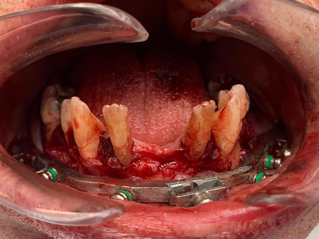
Step 2: Dentition Clearance
With the fixation base in position, the remaining failing dentition was removed followed by a palatal/lingual flap being raised and secured using a single palatal suture (Fig. 3).
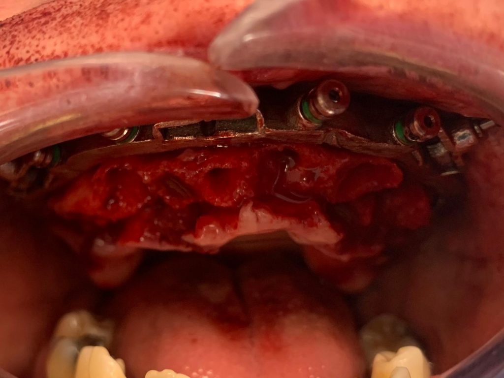
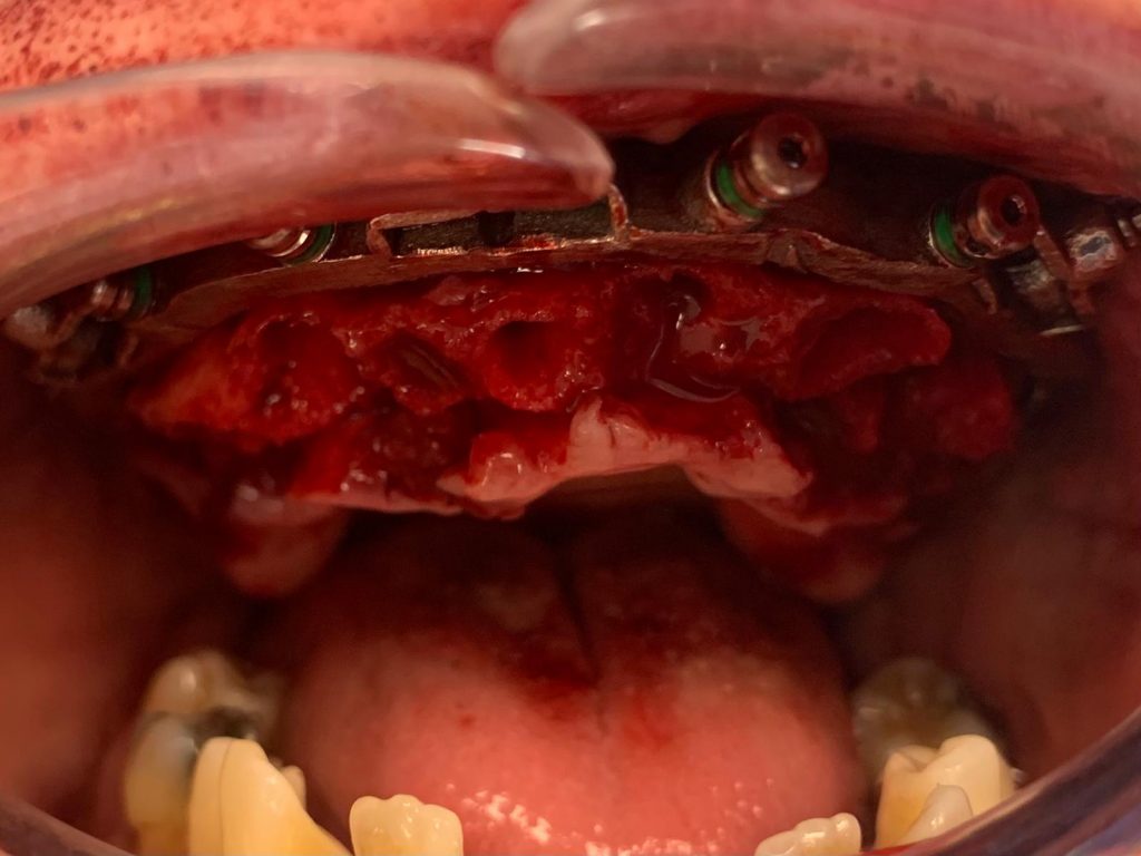
Step 3: Bone Reduction
The rationale behind bone reduction in the failing dentition is to optimize the alveolar ridge profile, disguising the transition between the prosthesis and the mucosa and the creation of the planned inter-arch space (Alzoubi et al. 2016). The ideal prosthetic dimension should be measured from the occlusal surface of the posterior teeth and the cingulum area of the anterior teeth to the fixture level. Reported figures for a FP3-style prosthesis range from 12-17mm.
The fixation base acts as the bone reduction guide. A large ceramic bur was used to reduce the bone to provide the planned inter-arch space for optimum prosthetic dimensions. The acrylic prosthetic carrier guide can be used to check that bone volume has been reduced as appropriate. Caution must be exercised to not over-reduce the bone as the implant angulation and position are based on the planned reduction.
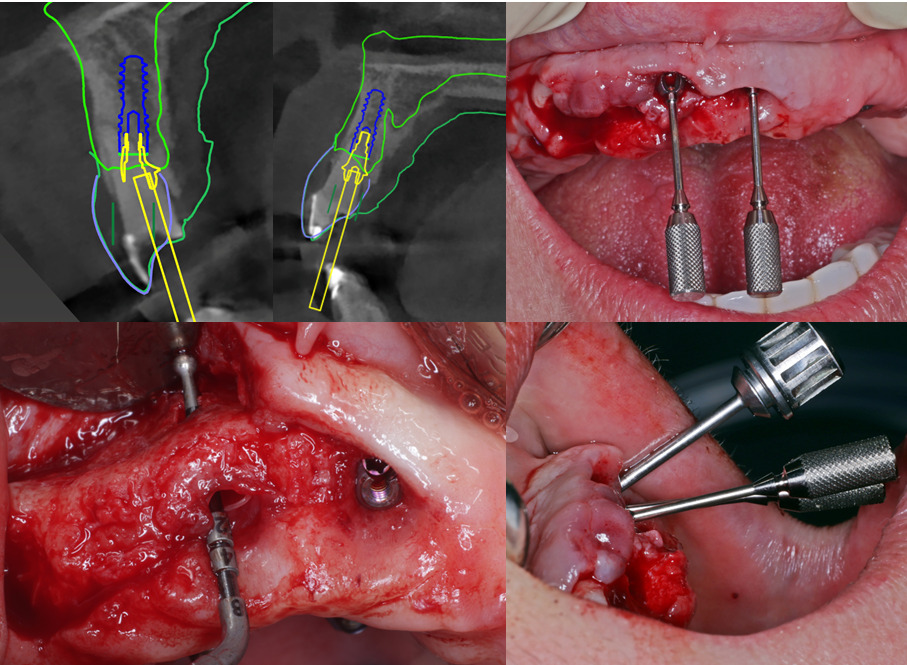
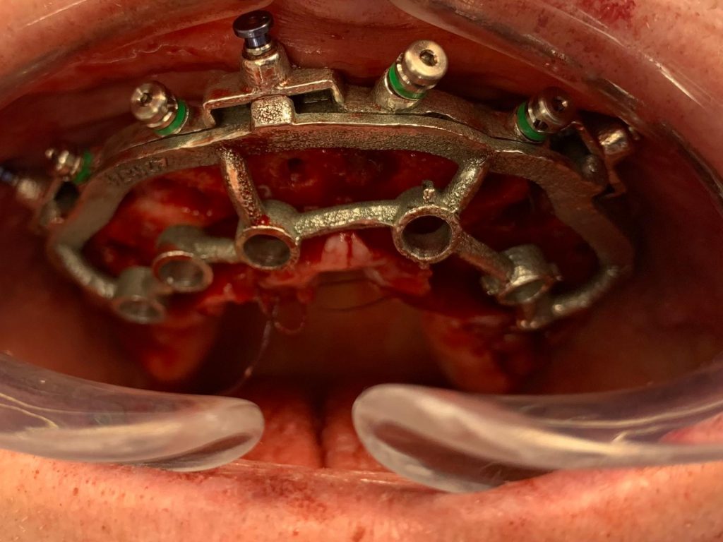
Step 4: Osteotomy Preparation and Implant Placement
The metal osteotomy guide is then secured to the fixation base (Fig. 4). In this case six Neodent GM Drive (Straumann Group) implants were placed. This implant was chosen because of its thread design and surface characteristics which allow for high primary stability in soft bone and extraction sockets. The Neodent GM guided kit was used to allow for fully guided implant placement. It is important when preparing the osteotomy for immediate loading to not over-prepare the bone or allow for any lateral movement with the drill. All six implants were placed to a final insertion torque of 45-50 Ncm. This ensures good primary stability and insertion torque which are critical factors in immediate loading cases (Ellis et al. 2020).
A threshold for immediate loading of four implants has been established to be 120 Ncm, with a minimum 30 Ncm per implant (Jensen & Adams 2012). In this case, all six implants exceeded this minimum insertion torque and had good primary stability for immediate loading.
Step 6 – Abutment selection
This prosthetic carrier guide now acted a stabilizer for the prosthesis to be picked up by way of plastic The osteotomy guide was then removed, and the prosthetic carrier guide was reattached. The case was planned for a mix of straight and angled abutments on all implants as there was need for angle correction. Both the osteotomy guide and prosthetic carrier guide have markings to indicate the rotation (indexing) of the implant and the direction of the angled multi-unit abutment screw (MUA). The bone was profiled at each implant to allow for passive seating of the MUAs and prevent contact with the bone. Neodent GM mini multi-unit abutments were selected and were torqued to the recommended 20 and 32 Ncm for angled and straight, respectively.
Step 7 – Pick up of Prosthesis and Conversion Appliance
This prosthetic carrier guide now acted a stabilizer for the prosthesis to be picked up by way of plastic extrusions (Fig. 5). The provisional acrylic prosthesis was seated, and each implant had a temporary cylinder placed on the MUA. The temporary cylinders and prosthesis were joined with a dual cure resin and allowed to set. The prosthesis was removed and left to be polished at the pick-up areas. The process was then repeated with a conversion appliance: a 3D printed copy of the provisional bridge which will act to transfer to the lab at the time of conversion – all the necessary information to allow the manufacture of the final zirconia prosthesis in two simple appointments.
Closure
Protection cylinders were placed on each of the MUAs and closure of the flap with simple interrupted resorbable sutures was completed. The maxilla treatment is now complete.
Mandible
The steps above were repeated for the mandible, where again six Neodent implants were placed. There was no need for angle correction with the MUAs. Both provisional prostheses were then seated, and the occlusion lightly equilibrated (Fig. 6). The screw access channels were sealed with light body silicone for ease of removal at the review appointment.
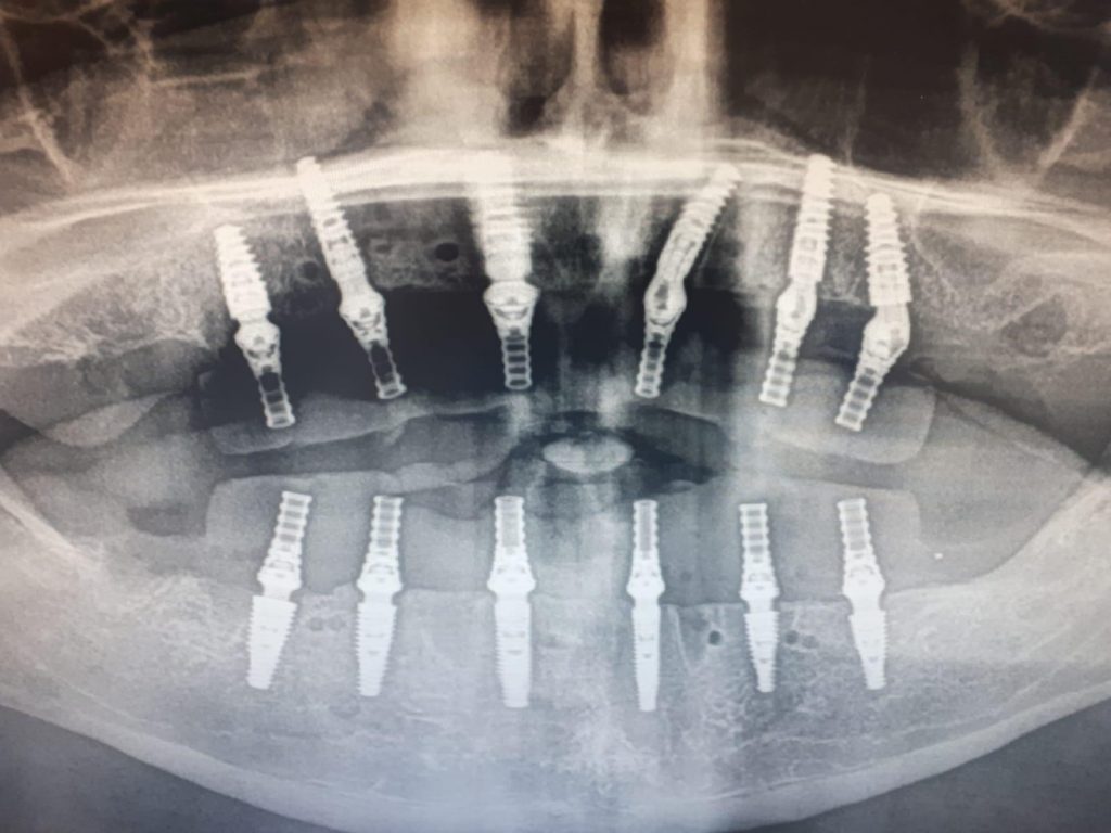
A post-operative orthopantomogram (OPT) (Fig. 7) was taken and checked for full prosthetic seating on all abutments. Post-operative instructions were delivered verbally and in writing. The total treatment time was approximately 5 hours.
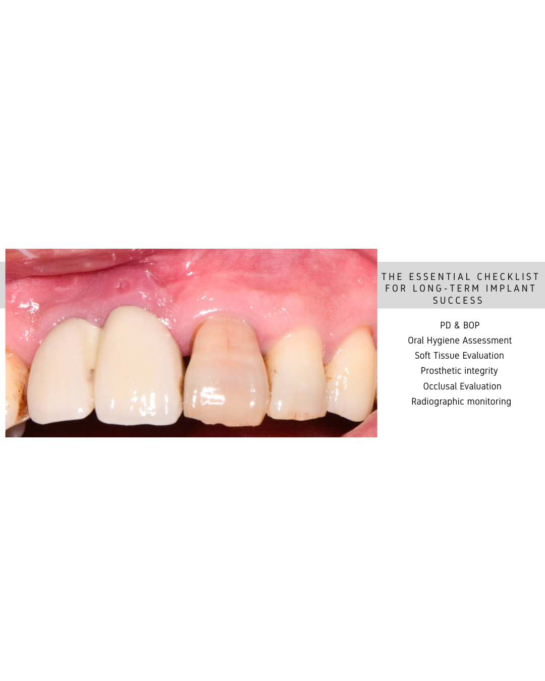
The patient was reviewed at 2 weeks post-treatment for prostheses removal and suture removal. The prostheses were re-seated after cleaning and application of chlorhexidine gel, and the screw access channels were sealed with composite. Post-operative photographs were taken to use as a baseline for final prosthetic design (Fig 8).
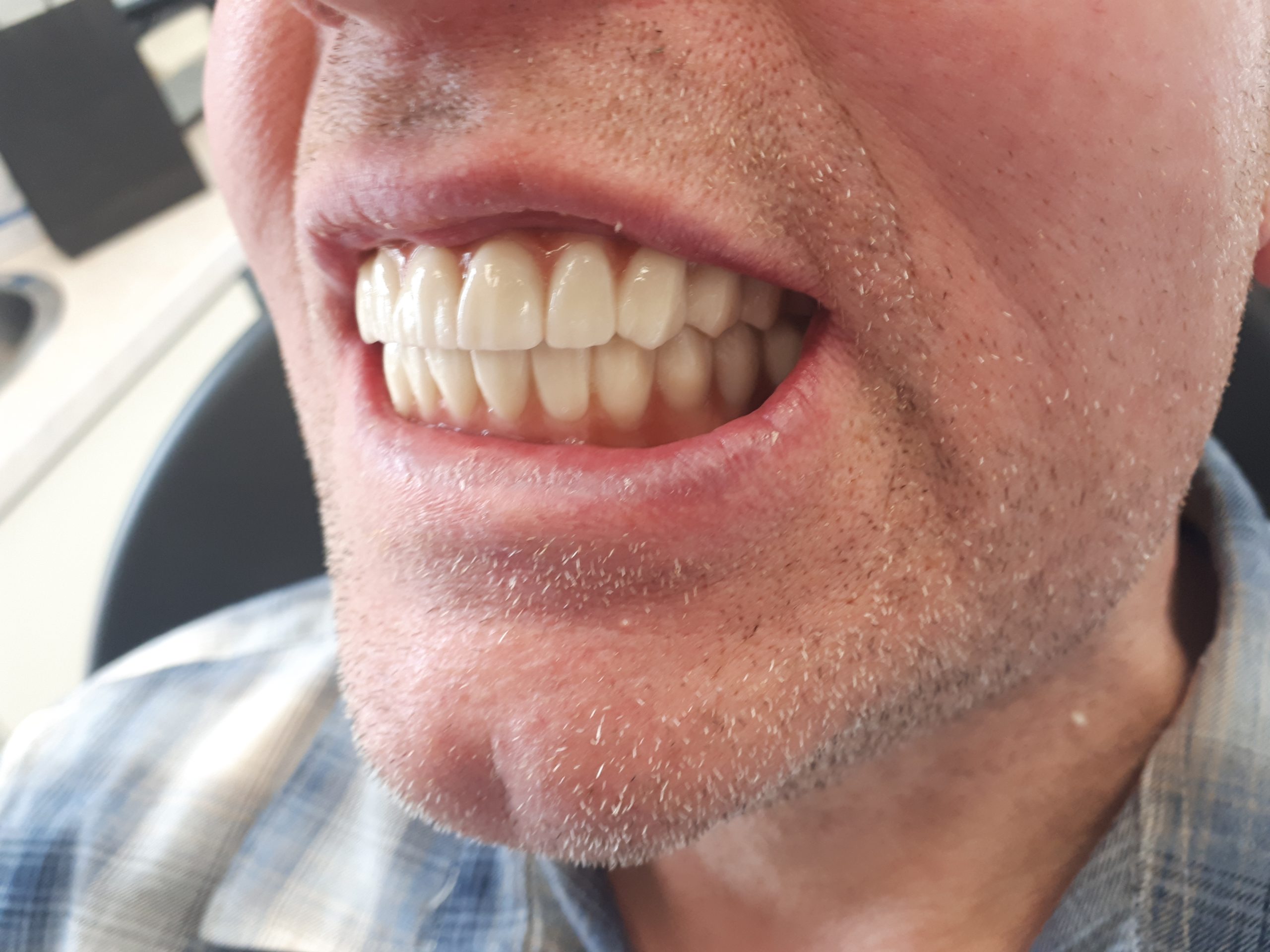
Conversion to Final
Following the 4-month period during which osseointegration is complete and hard and soft tissue healing is complete the patient returned for the conversion to the final prostheses. The current provisional prostheses were assessed for aesthetics, function, and phonetics. In this instance the patient had adapted very well to the new prosthesis and was happy to proceed.
The provisional bridges were removed, and all abutments had torque values checked and assessed if there was any need to change the height, all abutments were of an appropriate height in relation to the healed soft tissues.
The conversion appliance which was used on the day of surgery to replicate the provisional bridge was fitted on each arch. The occlusion on the conversion appliance was adjusted to replicate the provisional bridge. Adhesive was applied to the intaglio surface of the conversion appliance with a light body silicone wash. This technique picked up the new soft tissue profile in both the maxilla and mandible. A bite registration was taken. This information along with shade was sent to the dental laboratory for manufacture of the final zirconia bridges. The conversion appliance retains all the information the lab will require, implant and abutment position, occlusion, tooth shade, tooth shape and the new soft tissue profile.
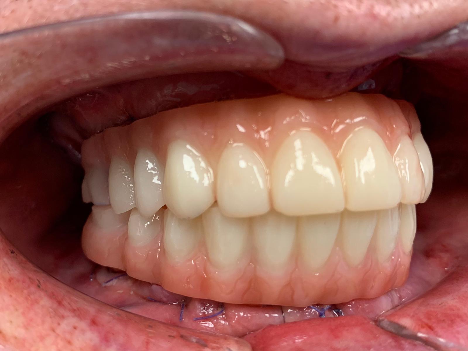
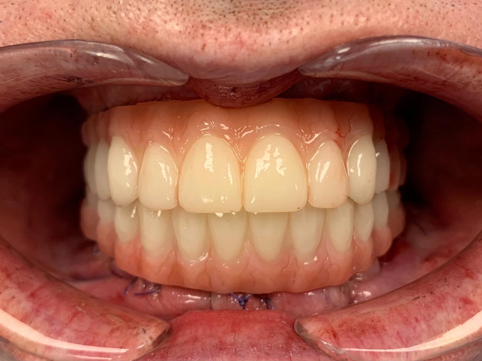
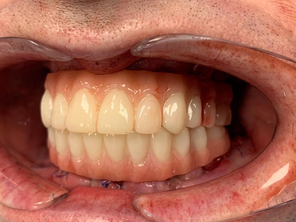
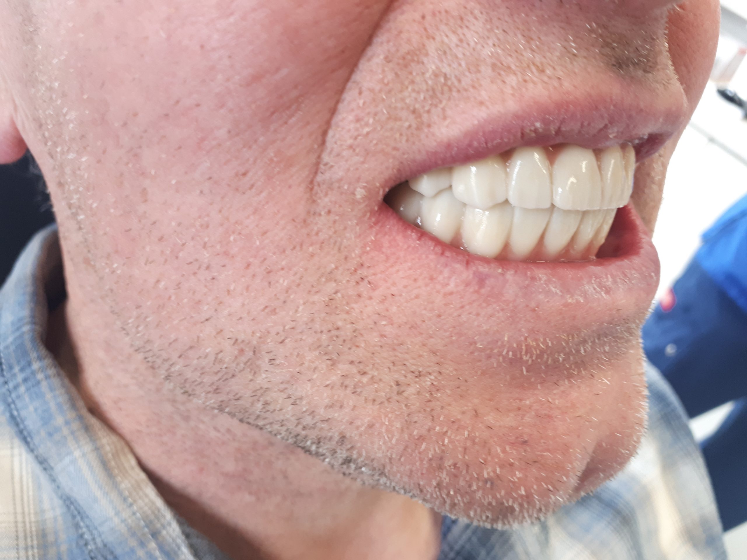
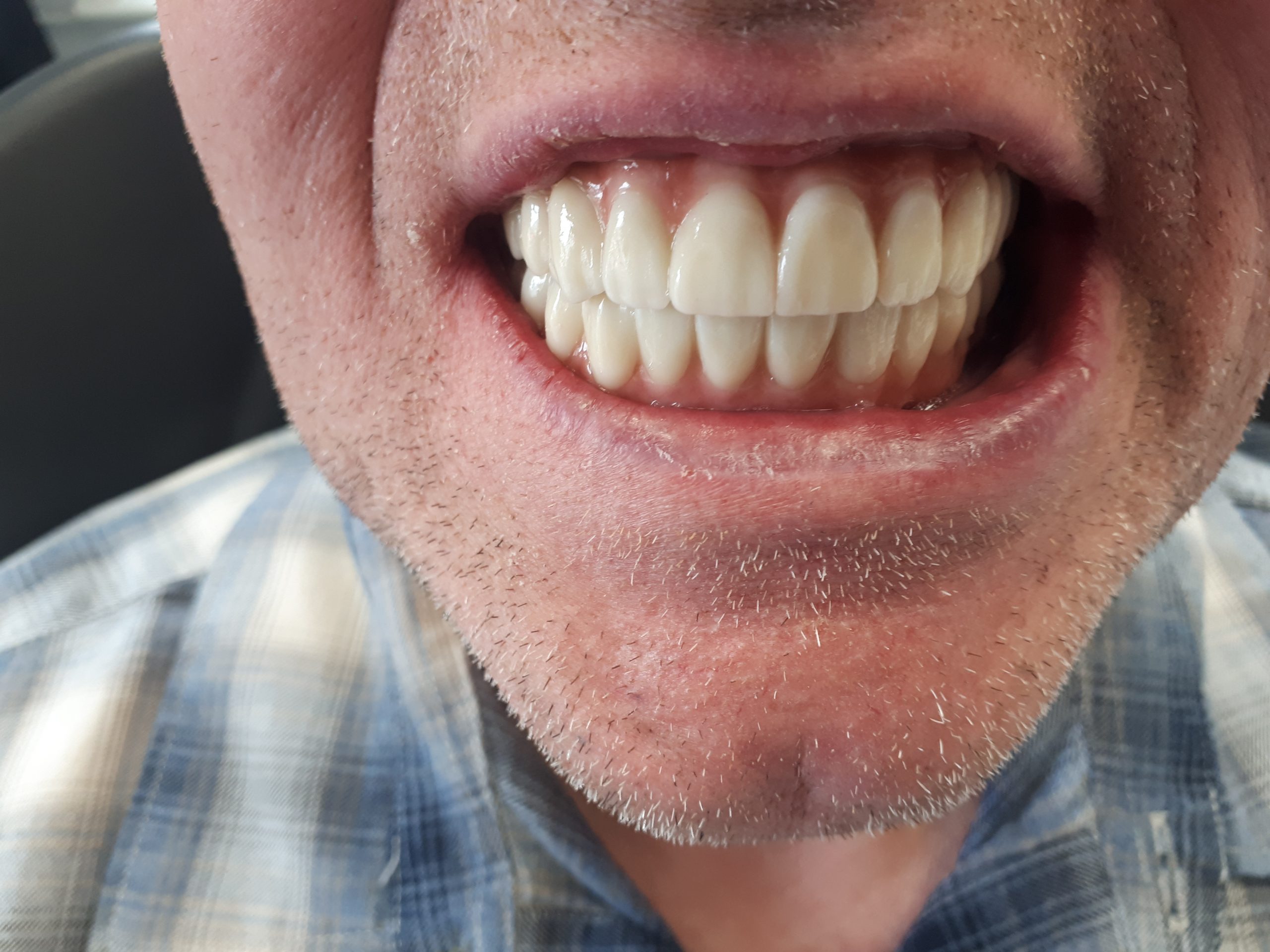
Fit of Final
Approximately 3 weeks after impressions with the conversion appliance the final bridges were returned and ready to be fitted. The provisional bridges were removed and again all abutments were checked for appropriate torque. A Sheffield test was performed on each bridge to ensure passivity by ensuring it was held on one screw. Both bridges exhibited a passive fit and were secured in place by the prosthetic screws. PTFE tape was applied in each screw channel before being sealed with composite. The occlusion was checked, and no adjustments were required (Fig 9). Final photographs and radiographs were taken. A water flosser was provided for oral hygiene and a review appointment was arranged.