Introduction
One of the key challenges in fabricating a full arch implant-supported prosthesis is the accurate transfer of the three-dimensional intraoral implant position to the laboratory models. The implant verification jig (IVJ), also known as an implant indexing device is an important component in such rehabilitations. It can be described as a solid structure that links the impression copings/temporary abutments to ensure the inter-implant relationship is preserved in the final impression. The Glossary of Prosthodontic Terms (GPT-10) defines the IVJ as a device used to make a registration record, or index, of dental implant positioning that is useful in facilitating subsequent transfers and verifying implant-to-implant relationships. The IVJ plays a crucial role in validating the accuracy of the master cast and ensuring the passive fit of the final prosthesis. This article aims to describe the importance of passive fit, functions, and materials used for the fabrication of the IVJ. It also presents a practical step-by-step protocol for evaluating passive fit using the IVJ, offering valuable insights for the readership.
Implant verification jig (IVJ)
Importance of passive fit
Passive fit or the ideal fit of the implant-supported fixed dental prosthesis to the underlying substructure is essential for the maintenance of osseointegration. Passive fit has been described as the level of fit that will not produce or cause any long-term clinical problems (Jemt T, 1991). A passively fitting framework should be free of strain and, in the absence of external load, should ideally place no stress on the implant components or the surrounding bone (Sahin & Cehreli, 2001).
The importance of achieving passive fit stems from the difference in the movement of teeth and implants. Under normal physiological conditions, natural teeth can move approximately 100 microns in their sockets due to the inherent resilience of the periodontal ligament whereas implants have a limited range of movement of around 10 microns (Buzayan MM & Yunus NB, 2014). Consequently, any misfit in the case of implant-supported fixed dental prostheses will be more destructive when compared to tooth-supported prostheses. A poorly fitting implant superstructure can result in various biological and mechanical complications.
The misfit of the implant superstructure arises from cumulative distortions occurring throughout the entire fabrication process of the final prosthesis, a concept known as the distortion equation. Theoretically speaking, a true passive fit could be achieved if the sum of all distortions equalled zero; however, studies have concluded that achieving an absolute passive fit is in practice not possible (Wee et al. 1999). Various authors have attempted to quantify the acceptable levels of misfit. According to Branemark (1985), it should not be more than 10 microns. Klinberg and Murray (1985) stated that a gap of up to 30 microns at the implant-abutment interface is acceptable, provided it does not cover more than 10 percent of the circumference. As per Jemt (1991), a misfit of around 150 microns is considered acceptable. However, a recent systematic review by Abdelrehim et al. (2024) concluded that the existing literature lacks sufficient data to establish a clinical threshold for an acceptable misfit. Additionally, the study highlighted that the mechanical response to misfit is more significant than the biological response.
Objectives of use
An IVJ is an imperative component of full-mouth implant reconstructions to ensure a successful prosthetic outcome. The main objectives of using an IVJ include:
1. To record the accurate 3D position and spatial orientation of implants and ensure an accurate transfer of intraoral implant positions to the laboratory.
2. To transfer occlusal relations to the articulator: An IVJ can be used as a foundation for fabricating an overlay occlusal rim to record accurate maxillomandibular relations, which directly affect the occlusion of the implant-supported prosthesis (Azpiazu-Flores FX, Mata-Mata SJ, 2021)
3. To serve as a quality control measure before framework fabrication and verify the fit of metal framework: An IVJ aids in identifying and correcting any misfits within the described range in the framework, helping to avoid costly remakes of the final implant prosthesis. By ensuring the framework aligns accurately with the implant positions, the IVJ minimizes discrepancies early in the process, preventing significant adjustments or re-fabrication after the prosthesis is finalized.
4. To serve as a guide for corrected cast procedure after framework sectioning: If the framework does not fit passively, it is sectioned to relieve stress and then rejoined using pattern resin. This reassembled structure functions as the IVJ and is used to create a corrected cast.
Types of verification jigs
1. Light-polymerizing acrylic resin jig
Photopolymerizable resin is a light-curing acrylic resin material used mainly for fabricating custom impression trays, base plates, and bite blocks in prosthodontic treatment. Photopolymerizable resin-based IVJs are commonly fabricated by the laboratory on master casts, that can be verified for accuracy by clinicians at the next clinical appointment.
2. Composite resin jig
Composite resin is used as a restorative material in modern dentistry. It has several clinical applications with numerous desirable qualities such as esthetic appearance, and adequate physical and mechanical properties. Clinicians employ composite-based IVJs as a chair-side procedure to fabricate quick jigs during splinted impressions as well as for verification of implant positions. One of the limitations of these materials is the polymerization shrinkage which ranges from 1.35% to 7.1% during curing and can be reduced by incremental technique.
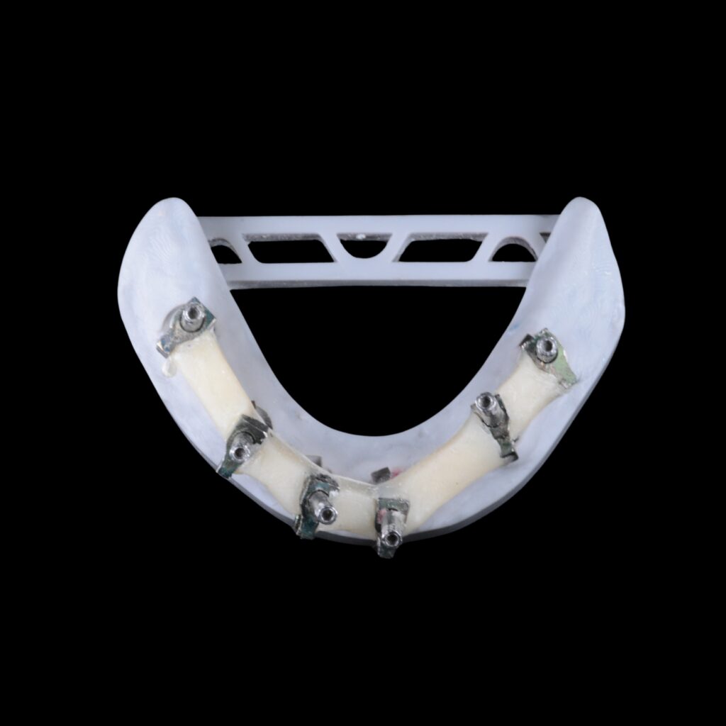
Fig.1: Composite resin jig
3. Pattern resin jig
Pattern resin is a self-curing acrylic resin that is used by dentists and laboratory technicians for making copings, custom-made posts and cores, bars, prosthetic attachments, clasps, and telescopic crowns, as well as in some soldering techniques. It sets quickly and can be modulated easily and is the ideal material for dentists and laboratories. Pattern resin has inherent polymerization shrinkage and 80% of the shrinkage occurs within 17 minutes, with insignificant changes after 24 hours. Additionally, Triad Gel, a urethane-dimethacrylate resin (UDMA) has been used for fabricating IVJs in the past but has found minimal acceptance (Majchrowicz M. 2019).
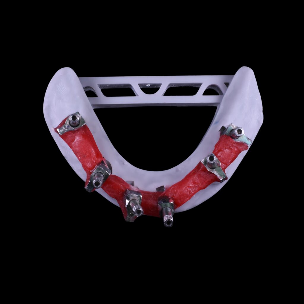
Fig.2: Pattern resin jig
4. Dental stone jig
Type IV dental stone possesses many ideal characteristics for a verification device, including high strength, high hardness, and minimal setting expansion. Unlike other IVJs, dental stone’s failure to withstand flexure results in its fracture, clearly displaying the misfit when an attempt is made to seat a nonpassive jig, clearly indicating an inaccurate impression or errors in the fabrication of the master cast.
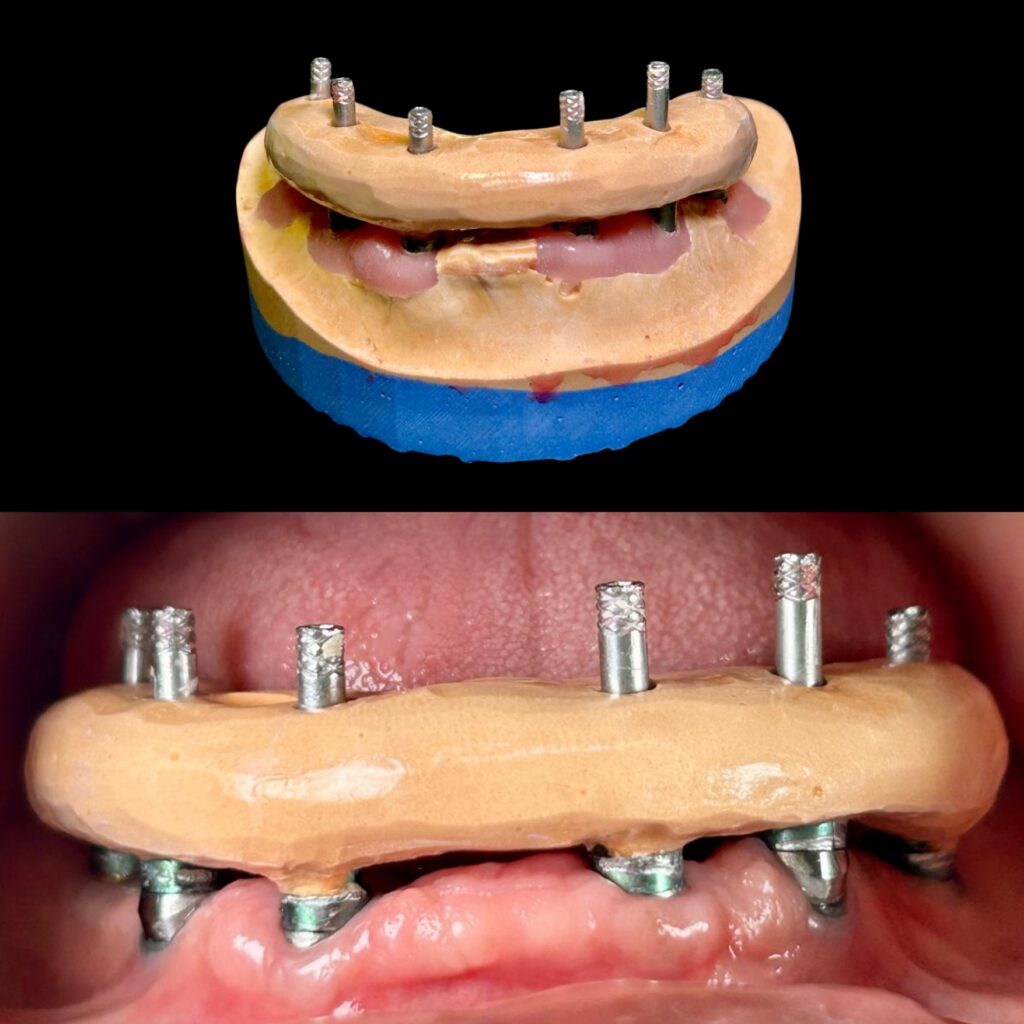
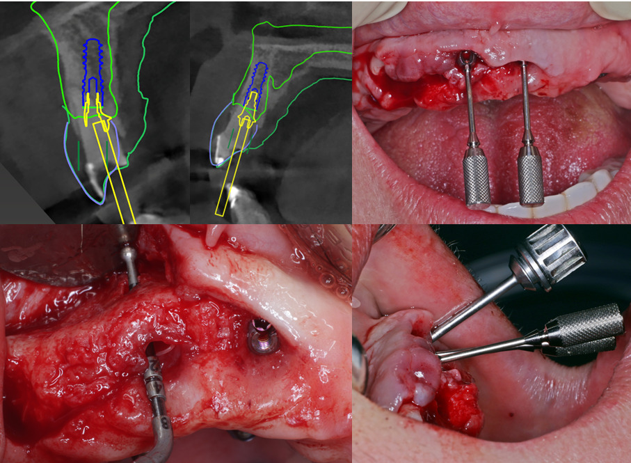
Fig.3 Top: Dental stone jig, Bottom: Dental stone jig being tried in the patient’s mouth
5. Metal-reinforced verification jig
One of the limitations of acrylic IVJs always has always been volumetric shrinkage and inherent flexibility, which could give false negative verification tests if the screws on temporary abutments are actively engaged. Metal-reinforced IVJs, which incorporate metallic elements such as used laboratory burs embedded in acrylic, can reduce the total resin volume needed, thereby minimizing volumetric shrinkage and decreasing the flexibility of the jig when tightening screws.
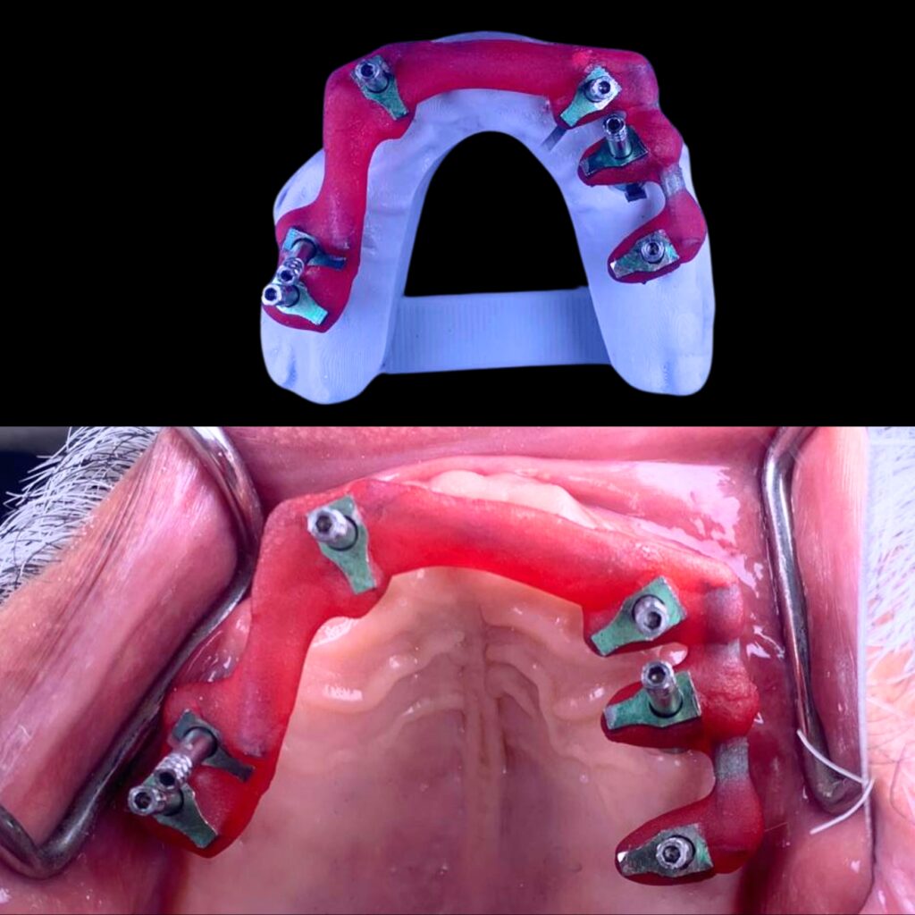
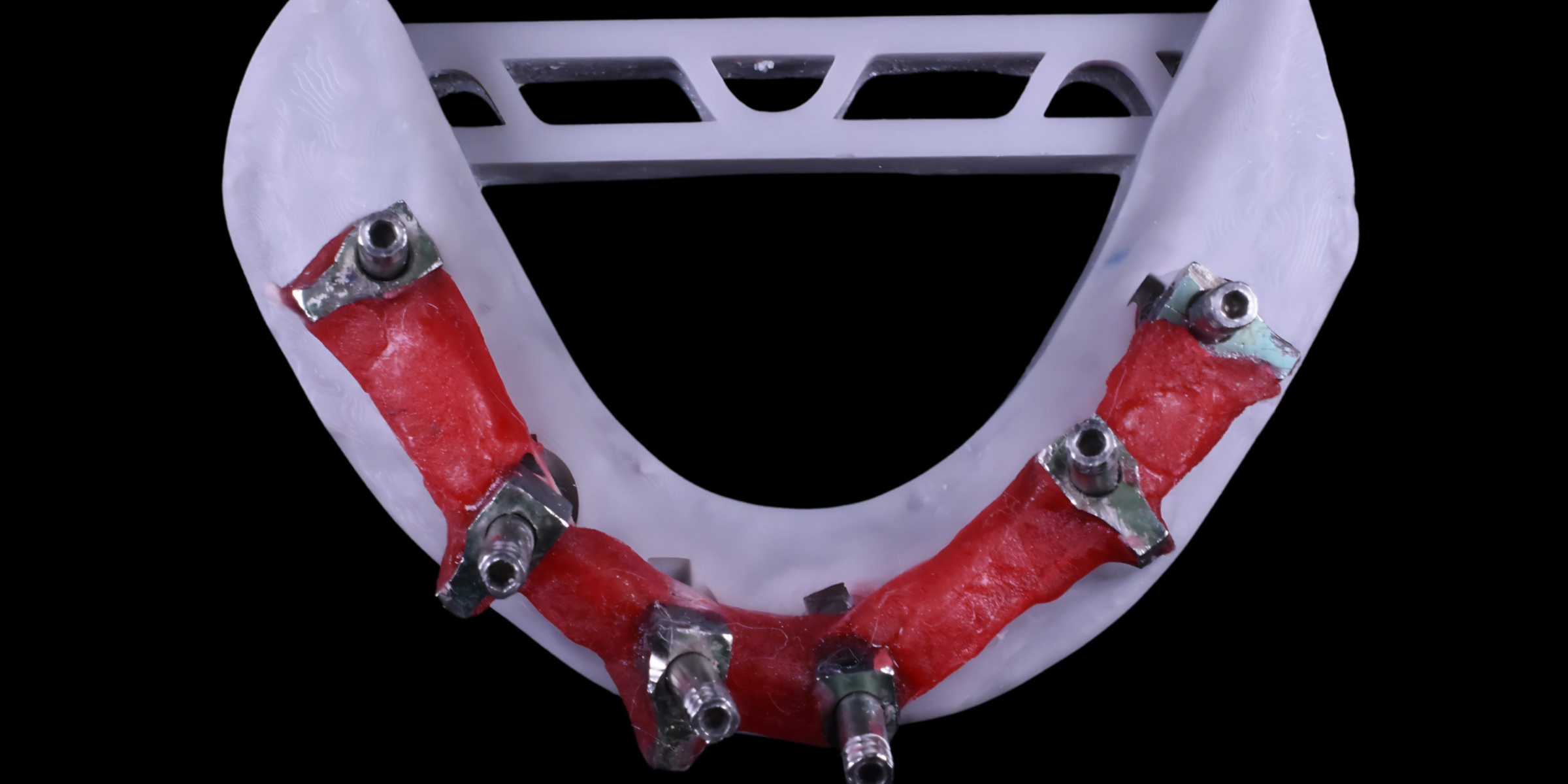
Fig.4 Top: Metal reinforced jig, Bottom: Metal-reinforced jig being tried in the patient’s mouth
6. CAD-CAM verification device
With advancements in technology, digitally fabricated variants of IVJs have become a valuable addition to modern dentistry. An intraoral scan is captured to design and manufacture a CAD-CAM verification device with a CAD software program. This allows dentists and dental laboratory technicians to digitally design and manufacture a verification device for nonsegmental implant-supported prostheses directly from an intraoral scan. The STL file of the verification device could be printed or milled. Light polymerizing resin can be used to connect an interim abutment on the printed definitive cast to facilitate the intraoral handling of the CAD-CAM verification device. Either auto-polymerizing or light-polymerizing resin can be used to connect the interim abutments with the CAD-CAM verification device, provided that the selected material is properly polymerized.
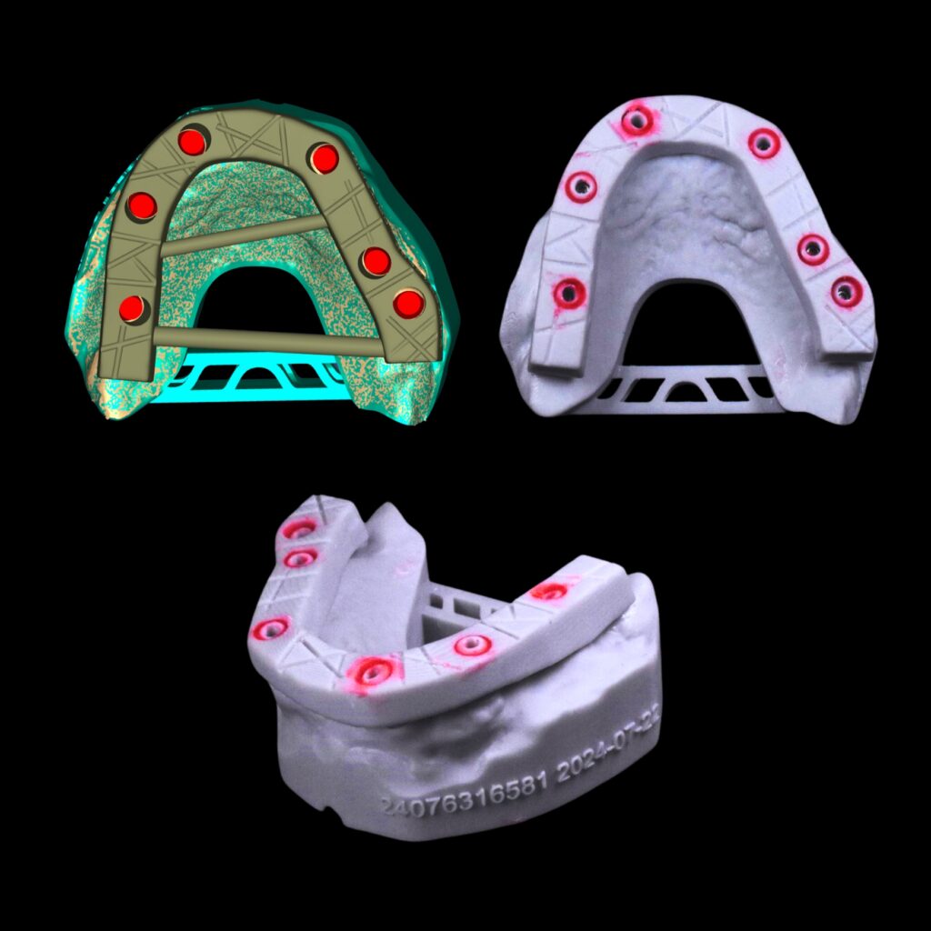
Fig.5: CAD-CAM Verification jig
7. Reverse verification jig
More often an IVJ is made on a master cast and tried in the mouth to verify the accuracy of the impression. The authors propose a new term – Reverse Verification Jig (RVJ). RVJ is made during impression-taking appointments, following all the steps to make sure there is minimal shrinkage. The master model – either a stone model or a digital model can be fabricated to check its accuracy with the RVJ made during impression appointment. If a discrepancy is found, a new impression needs to be made. In the case of no discrepancy, a second IVJ on the model can be made to double-check intra-orally to further evaluate the accuracy of the impression and the model. An RVJ becomes vital in the case of immediate loading complete arch cases where the provisional prosthesis need to be delivered within a week.
Tests used to assess passive fit
The literature highlights various tests to assess passive fit, but there remains a lack of consensus and uncertainty regarding the choice of tests or their sequence. To evaluate passive fit, we have compiled a list of pertinent and clinically significant tests in a sequence that most often simulates a clinical situation.
Step 1 Visual inspection
Visual inspection is practically the first step to assess whether an IVJ fit is acceptable and can be significantly enhanced with better lighting and magnification. However, the ability of clinicians to determine an acceptable margin opening varies. This approach is heavily reliant on the margin’s position as well as the clinician’s optical acuity, physical dexterity, and experience. As an initial step to evaluate the fit of an implant framework, visual inspection and tactile sensation with a dental explorer are frequently employed in conjunction with other techniques.
Step 2 Finger Pressure Evaluation
Following visual inspection, the finger pressure evaluation approach is quick and effective for identifying severe implant-framework mismatch. The prosthesis is manually seated using finger pressure given alternately to one terminal abutment and then to the other. By looking for lifting or distortion, this alternating pressure assists in locating any fulcrums that may be present – the prosthesis can then be described as rocking. When there are subgingival margins or short-span implant-supported fixed dental prostheses, this approach can be challenging to interpret.
Step 3 Tactile sensation
Using a conventional dental explorer, Hayashi et al. (2005) have demonstrated that tactile sense is more effective than assessment by eye at identifying subtle differences. The size of the explorer tip has a significant impact on this technique’s sensitivity. Dental explorers have tip sizes ranging from 60 to 120 μm, making it challenging to detect gaps smaller than this range. Additionally, studies have shown that dental explorers are more effective at identifying horizontal discrepancies than vertical gaps, which limits their reliability in assessing passive fit.
Step 4 Sheffield Test
The “Sheffield Fit Test” was developed in the early 1990s at Sheffield University, School of Clinical Dentistry and was used to assess the suitability of fit of both wax/acrylic patterns and cast frameworks on the model and in the mouth. Contrary to popular assumption, the Sheffield Fit Test is not attributed to an inventor in the traditional sense; rather, its name comes from the university where it was developed. It is an effective test for clinical assessment of framework fit, also known as the one-screw test. The superstructure is considered to have a clinically acceptable fit when one screw on the distal abutment is fully tightened without leaving space between the other abutments and cylinders. For long-span frameworks, where the vertical gap is likely to be accentuated at the opposite abutment, this method works particularly well.
When the margins are supragingival, direct vision and an explorer can be used to measure the vertical gap on the unscrewed abutments; when the margins are subgingival, periapical radiographs can be used. The Sheffield Test’s drawback is that it cannot identify differences in three dimensions and frequently masks them if the distortion takes place in the horizontal plane.
However, over time, many of the test’s fundamental components have been lost or misused, and the test is frequently administered wrongly. To ascertain whether a discrepancy in fit occurred and whether it was serious enough to necessitate a redesign of the framework, the original Sheffield Fit Test was intended to be in two sections. Often operators who continue to utilize this test merely apply the first section, and frequently execute it incorrectly. This may result in needless framework redesigns. Below is a description of the Sheffield Fit Test Part 1 and Part 2:
Sheffield Fit Test Part 1:
Fitting accuracy is initially assessed by finger pressure to seat the framework onto its abutment/implant replicas before lightly tightening one of either of the two most distal abutment/implant screws using the appropriate screwdriver. It is important to note that the clinician should not use a torque wrench to perform this test and should refrain from using laboratory screws or impression coping screws. They tend to lack the precision of final clinical retaining screws. Using this single screw connection, the entire framework should exhibit accurate horizontal and perpendicular alignment when examined under magnification, the preferred magnification would be at 20x.under light microscope. The evaluation under a microscope is limited to evaluation on a model before clinical trial. Most practitioners, however, use the naked eye to evaluate the model before proceeding to clinical trial.
If the framework passes the Sheffield One Screw test, screw tightening can commence with any screw, as the framework demonstrates passive fit across all areas. Occasionally, a vertical discrepancy may appear between the framework and an implant or abutment replica distant from the test screw, which can be further evaluated and confirmed as a satisfactory passive fit using Part 2 of the test.
Sheffield Fit Test Part 2:
If a suspected fitting discrepancy can be closed by pressure from the edge of a 13mm wide strip of modelling wax at a room temperature of 20ºC, representing a 20KN/m2 (0.02 MPa) pressure load on the implant, without the wax distorting, then the fit is clinically satisfactory without further attention. Finger pressure should be exerted on top of the strip of wax about 1.5 to 2 cm from the point where the wax contacts the framework.
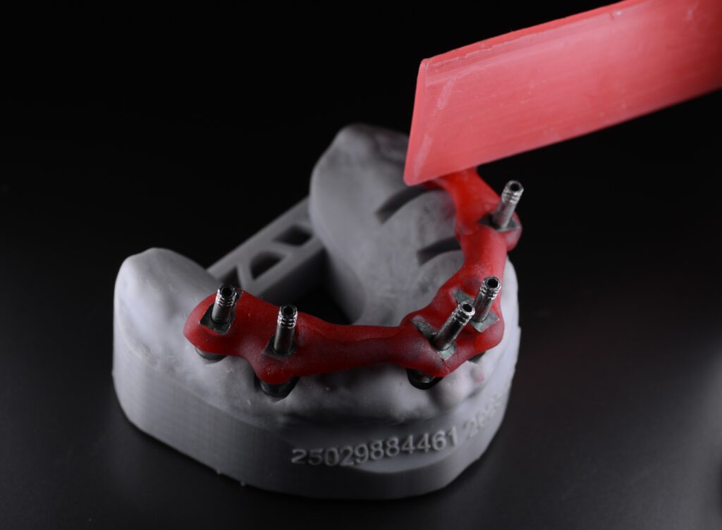
Fig. 6: Modelling wax used to check fit of IVJ on a model
If the amount of pressure needed to close the gap exceeds finger pressure (⁓ 0.02 Mpa), it could indicate that the force required to close the gap represents enough stress on the implants and surrounding bone to cause damage and potential loss of osseointegration or breakage of the retaining screws. Hence this fit is not considered to be acceptable, and the framework should be re-made.
In cases of non-parallel placement of implants (refrain from using it in case of extremely angulated implants), the clinician needs to tighten all the retaining screws down evenly together using finger pressure and not to tighten one screw down fully to maximum torque before tightening the rest.
Another consideration about the controversy of the one-screw test (Sheffield Fit Test) in the authors’ opinion is that when testing a framework or IVJ on the maxillary arch, the inherent weight of the framework or IVJ along with gravity can make it seem that there is a misfit at the other distal end. The same framework/IVJ might sit passively on the benchtop when tried in on the model, giving an impression of a misfit. Although never addressed, it is something commonly experienced by clinicians.
Step 5 Modified Sheffield Test
The Sheffield test, as described above, is not effective for nonplanar connection geometries, especially if the positioning of such geometries by the dentist also diverges vertically. Even if the mesostructure achieves a perfect fit after all screws are tightened, a gap will inevitably appear due to the geometry (inclined plane) when secured with only a single screw. Therefore, another procedure, a modification of the Sheffield test which applies to all types of connection geometries is used. Place the IVJ/mesostructure on the implants with the screws inserted. Then, starting from the center, screw all the screws in evenly and carefully with identical force (approx. 5 Ncm) until the IVJ/mesostructure sits in the final position. Afterwards, carefully unscrew all the screws except for one. Then perform a check to see whether a gap has formed between the mesostructure and the implants in which the screws were loosened. The dentist should then take an x-ray at the final try-in in the patient’s mouth as a final check to ensure that the mesostructure fits.
Step 6 Radiographs
Radiographs have been used to evaluate framework fit with periapical radiographs offering more detailed views of specific areas and panoramic radiographs to provide a comprehensive overview of the entire arch as required in complete arch rehabilitation cases. The value of the radiographs becomes more important in the case of subgingival framework margin assessment. The film should be as perpendicular as possible to the long axis of the implant-abutment junction to optimize the accuracy of the radiograph. Poor alignment of the film could result in overlapping between the framework and the abutments which may hide any existing gaps. Cameron SM et al. (1998) advocated maintaining the tube head at fewer than 20 degrees from perpendicular to the long axis of the implant to achieve a diagnostic radiograph, regardless of the angle of the film.
Many in vitro tests are available in the form of photoelastic stress analysis, strain gauge analysis, finite element analysis, microscopic measurements, photogrammetric technique and coordinate measuring machine tests. However, these tests are done in a non-clinical setting which is not applicable for clinical chairside evaluation.
Where do IVJs fit in the age of digital innovation?
In the modern implant prosthetic rehabilitation, there has been an increased amount of complete arch implant fixed dental prostheses utilizing intraoral scanners (IOS) with fully digital workflows. One common technique is to attach scan bodies to implants and to transfer the implant’s three-dimensional (3D) position captured with IOS. With the rapid advancement and evidence for full digital workflows, digitally designed and milled verification jigs are bridging the gap between the analog and digital workflows and playing a crucial role in verifying digitally acquired intraoral information without the use of the labor-intensive conventional resin verification jig. Another advancement that helps in transferring the intraoral position of the implant position for the fabrication of definitive prosthesis are the reverse scan bodies (Straumann RevEX, Straumann) introduced by Papaspyridakos et al. (2023). The recently developed reverse scan body protocol has allowed for an alternative approach to the digital acquisition of implant positions in fully edentulous patients. Bedrossian et al. (2023) documented the use of reverse scan bodies attached to conversion prosthesis to record 3D implant positions and prosthesis contours extraorally. To address the concern regarding the inherent flexibility of the resin used for conversion prosthesis, the authors also verified the implant positions using the digitally milled IVJ acting as a crucial quality control check. In this digital era, it is crucial to advance and adopt new digital workflows in our clinical practice to enhance our patient care. In the coming years, we envision digitally milled verification jigs replacing traditional methods.
Crockett et al. (2023) proposed the use of a dental implant indexing device (OptiSplint; Digital Arches LLC) as a versatile tool serving dual purposes: it acts as a scan body for complete arch rehabilitation and also as a physical device that can be scanned or used to create a verified stone cast. OptiSplint can be described as a scannable verification jig that eliminates the need to fully rely on an intraoral scanner for relative implant position accuracy while also allowing the clinician to use a near fully digital workflow chairside. Both of these are digital and unique innovations of IVJ but they require long-term follow-ups to confirm the accuracy of the same.
Conclusion
As contemporary implant dentistry increasingly embraces digital workflows, the traditional analog implant verification jigs are being replaced by milled verification jigs. While advanced technologies like photogrammetric scan bodies and reverse scan bodies challenge the necessity of verification jigs in modern workflows, these jigs remain a valuable tool for quality assurance. They help ensure passive fit and minimize the risk of costly remakes of the prosthesis, serving as a critical step before fabricating expensive definitive restorations.