A surgical guide carries all the information of prosthodontically guided implant planning. It is the summarized concept of all parties involved in treatment planning: lab technician, prosthodontist, and oral surgeon. An accurate and practical surgical guide is one component to place implants in an ideal position.
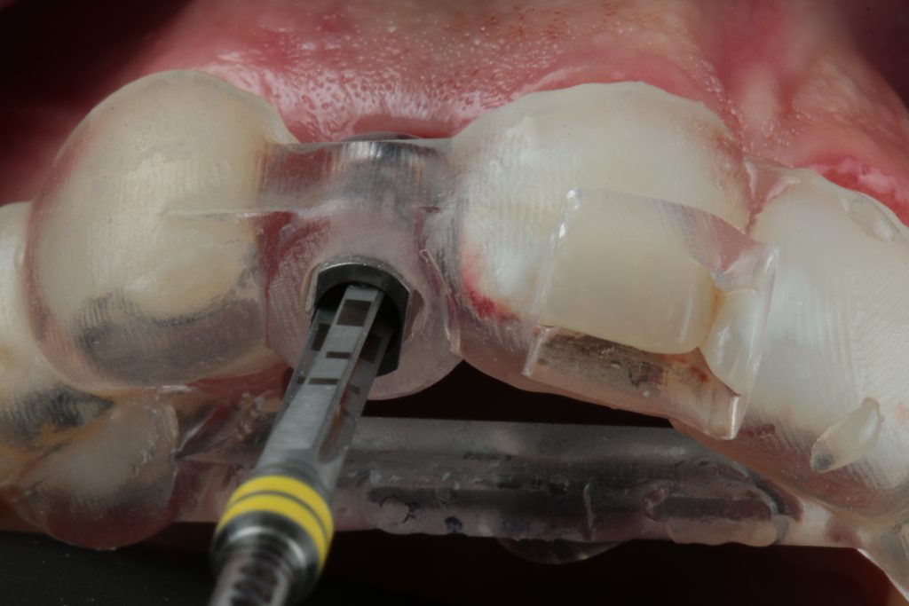
The transfer of the digitally planned implant position can be achieved with a guided pilot osteotomy, or fully guided osteotomy and implant placement. The drill guide may also contain information about the future prosthesis or future diagnostic wax-up (Fig. 1). The best strategy for each treatment is chosen by the clinician and the design of the surgical guide is adapted to individual requirements.
This article will give you 10 easy tips and tricks (Hint, Trick and Tip) to help you achieve the best precision possible to boost clinical results.
1. Material selection
Fabrication of a surgical guide can be carried out using traditional vacuum and thermoformable systems. Although these systems are still used for simple cases, fast paced technological developments led to workflows in which drill guides are designed virtually and fabricated with computer-aided technologies. We now have the possibility of using two different types of technologies; subtractive technology (Fig. 6) and 3D printing additive technology (Fig. 2).
My tip is that both produce surgical guides of acceptable quality, but the latter presents better detail, passive seating, and the possibility of recreating angles that a milled system does not allow (even with 5 axes). There are numerous advantages to 3D printing guides, one of them is the fact that most implant planning softwares are calibrated with 3D printers, allowing for an interconnected workflow resulting in high quality guides.
For these reasons I favor printed surgical guides and used them in most of my treatments.
2. Guide planning and construction
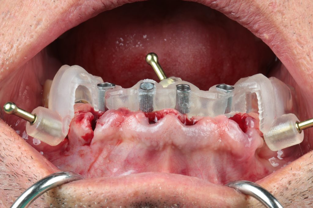
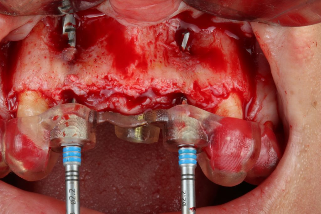
Hint: When constructing a guide, important aspects such as implant positions and bone dimensions must be addressed. In my practice, having a visible surgical field is paramount (Fig. 3). Place a surgical guide so that it doesn’t disturb the field of vision of the surgeon or the dental assistant.
Having a guide that fits this purpose will enable a correct osteotomy, saline irrigation, and ensure an accurate transfer of the digitally planned implant position to the surgical field.
So for me one trick is to build a surgical guide with a slim or cut-out buccal portion and stable parts that are crucial for guide positioning, sleeve openings, bone anchor pins, tooth, mucosal or bone-support areas.
Tip: The final shape does not have to be designed virtually. There are several ways to finalize the surgical guide during post-production. Most implant planning software directly produce a STL file, with others the design may be performed in a free software.
3. Tooth-supported drill guides
Hint: When going for static surgical guides, the implant professional can choose several supporting structures: the bone, the mucosa, the teeth, or bone anchors/pins.
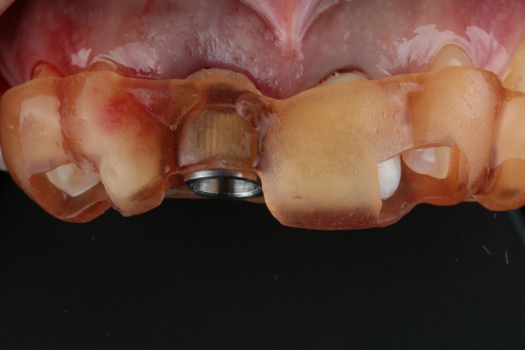
The tooth-supported guides are one of the most often used type of guide and ranked second in the available literature for accuracy of the transfer of the planned implant position (Tahmaseb et al. 2018). With tooth-supported guides, one trick is to be sure that you open inspection windows to allow visual confirmation of the correct seating. There are many places for inspection windows, but in my opinion the best area is the teeth (that shows interproximal area) (Fig. 4).
Hint: Another potential problem in tooth-supported surgical guides is the interproximal space available (between teeth) to use fully digital workflows.
When going for fully guided techniques don’t forget that in the majority of implant systems there is a minimum diameter of 5 mm for drill sleeves. So, one trick is to be sure that you have this interdental space in the presurgical appointment. If you don’t have it, it’s a good opportunity to see if you can do interproximal guide plans (in the adjacent) to optimize the contact points and at the same time, allow space for the guide and the sleeve.
This item is one (of many) that can be responsible for guide misfit. The tip is if you don’t have space and interproximal enamelplasty is not an option, maybe this is a good case for pilot drilling only, a classical approach (without a surgical guide) or you could even consider revising the treatment plan to include orthodontics and open the space.
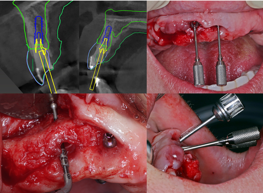
4. Drill guides supported by bone anchors/pins
Pin-supported guides are seen in the literature as having the most accurate transfer of the planned implant position to the surgical site.
Hint: Although they were initially known for full-arch implant therapy, their use is not exclusively for that purpose, meaning that any guide can have a bone-stabilizing pin.
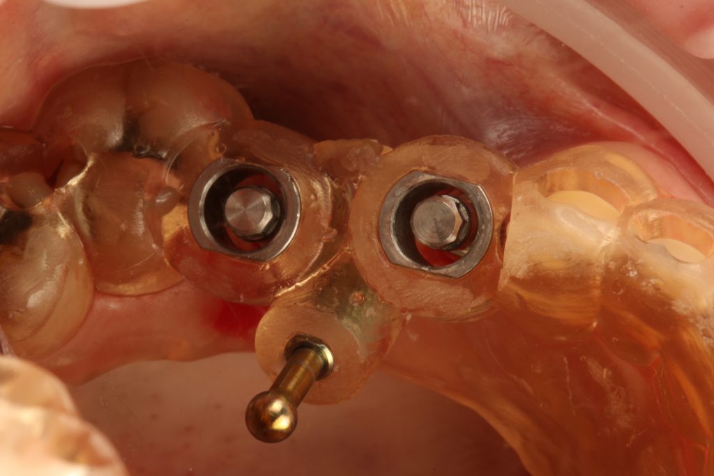
Single and partial rehabilitation guides can also benefit from this increased stability, so my Tip is to place an anchor pin if you feel that your guide stability will be in jeopardy (Fig. 5).
One trick in maxillary arches is to place pins on the palatal side of the guide or on the buccal aspect adjacent to the surgical. Sometimes I even go for a mixed situation.
Palatal guide pins have several advantages:
1. Do not take up buccal space
2. Can compensate the buccal force of the surgical instruments that go through the guide
3. Allow buccal opening of guides
In the mandible, a stable and safe place to anchor a drill guide is the interforaminal buccal bone. In the mandible we use short stability “arms” that can embrace adjacent teeth (specially on the lingual part of lower central incisors as a substitute for anchor pins. We do this mainly due to lingual concavities and mental foramen that sometimes don’t allow for proper anchor places.
Hint: There are several bone anchor diameters available in the market and almost all implant brands have their own that has to be selected when designing the drill guide. A good “one trick” idea, is to use the “slimmest“ anchor pin possible to avoid extra morbidity and difficulties in inserting into cortical bone.
Hint: Placing guided pins on the palate seems easy but be careful with the direction of the anchor pins. So my tip is to avoid a distal angulation of anchor pins – they will be difficult to place (due to the size of each pin) or even impossible due to mouth opening.
5. Pilot drill static guided surgery
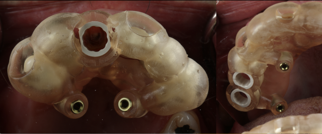
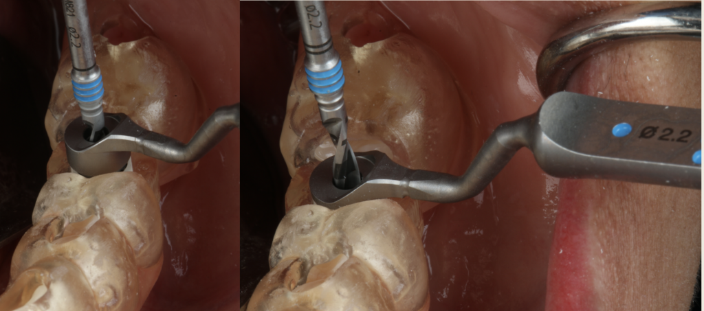
Hint: Pilot drilling refers to a technique that allows to pinpoint the correct 3D position of the implants in relation to the teeth and make the first osteotomy (2.0) through a drill sleeve (Fig. 6). Although in most cases of pilot drilling there is no problem in the drilling osteotomy, remember that implants with lengths of 14 mm and 16 mm set at 2 mm subcrestally sometimes don’t allow for standard drill lengths.
6. Fully guided static guided surgery
When using static guided surgery in a fully digital workflow, it is necessary to be aware of deviations reported in the literature, regarding implant depth and lateral deviation between planning and actual position.
Hint: Implant depth is one feature that can be a potential problem. Not going to the adequate length of the osteotomy may expose the implant rough surface to the oral environment and affect implant survival and potentially cause peri-implant problems.
My tip is to always perform a radiographic exam and assess the depth of your final implant position. If required, the implant position should be corrected. It is better to correct on the day of the surgery than to wait for short or mid-term complications.
If we are on the +1-mm handle (and want to go deeper), we can always turn to a longer length drill than the one used. If we were on the +1-mm handle and on the longer drill (meaning that there is no more room to go with different instruments), then it’s a good idea to go with a classic protocol and postpone the use of a guide and digital workflows (Fig. 7).
Hint: The lateral deviation is the second parameter that may have a direct impact on the crown/bridge position. It depends on many factors including the alignment of intraoral scans and CBCT during planning, guide stability and surgical performance.
One trick is, to master one digital implant planning system to understand its workflow when aligning intraoral scans and CBCT data.
Specific care should also be taken when acquiring CBCT to achieve optimal image quality. This depends on the system, the operator and the patient position. Take the image, always with cotton rolls on the vestibule to retract the cheeks and follow the guidelines recommended for the machine.
Another important factor that may affect deviation, is the stability of the guide. Having a tooth/mucosa supported guide with the aid of bone fixation pins in the palate can be an interesting solution for stabilization since this can prevent buccal movement in the drilling phases and in implant installation.
In posterior maxillary implants, the guide may be displaced by rotating around a transversal axis. To prevent this displacement a distal skeletal anchorage should be included posterior to the last sleeve.
7. Sleeve selection
For the majority of systems, there are two separate parts to a surgical guide: the guide itself and the drill sleeve. The first is produced using additive or subtractive computer-aided manufacturing, the second is provided by implant companies and is prefabricated. The two parts must merge with a perfect fit for a smooth and precise surgical procedure.
Hint: When a sleeve is placed into a surgical guide, it is crucial that it has sufficient and secure retention within the guide to allow free movement of the drill with the greatest possible control. Therefore, sleeves must be correctly calibrated so there is enough space for a passive but friction fit when inserted.
One trick to avoid misfits and the need to do extra bur refinements of the guide sleeve hole (that can lead to imperfections that can affect precision) is to print a calibration sleeve guide to correctly calibrate the planning software with the 3D printer.
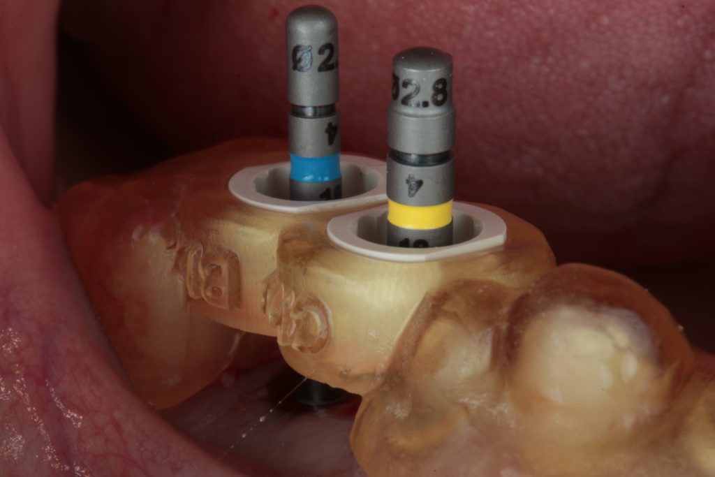
The idea is to have a matrix of differently sized holes in 0.1 mm increments and see which hole has sufficient retention to allow for proper surgery. After choosing the correct size, set your 3D printer parameters in the planning software and you have a calibrated guide. It is important to calibrate all the sleeves: the 5-mm sleeves for a fully-guided workflow, and the 2.2 and 2.8 mm sleeves for pilot drilling as well as the sleeves for the bone anchor pins.
There is no rule for how many times to print the calibration guides, but my tip is that this should be done regularly (when there are liquid changes in the 3D printer) or when there are software or hardware changes.
8. Fully guided in full-arch rehabilitation
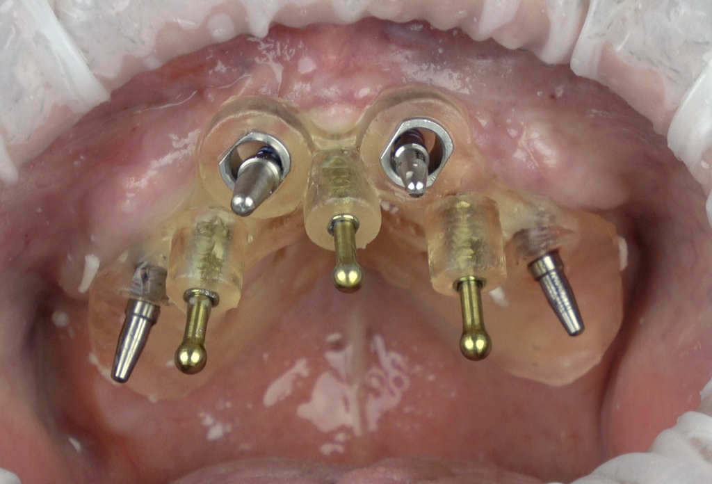
In full-arch rehabilitation, we have the added function of the surgical guide to transfer diagnostic wax-up information to the surgical field.
Hint: one of the initial difficulties is merging the prosthesis with the residual bone, which is dependent on wax-up/prosthesis fabrication, DICOM-file acquisition and STL/DICOM merging.
In some softwares, merging the prosthesis with bone can be performed using a CBCT exam of the patient and the CBCT DICOM files from the prosthesis, others require the DICOM from the bone and the STL from the prosthesis, yet others accept any modality.
My one trick is to have proper DICOM files of the prosthesis. The new generation of CBCT systems have already incorporated the possibility of scanning the prosthesis, but if you have a CBCT system that doesn’t, it is a good option to have a tyrofoam support to place the prosthesis and reduce the kilovoltage.
With respect to DICOM files, you can take them from the final acrylic prosthesis, but the wax try-in can also give you very good image results and resolution.
Hint: In full-mouth rehabilitation, merging bone with prosthesis is made by placing radiographic markers on the prosthesis, creating special landmarks to merge these two in an implant planning software.
One trick is to have gutta-percha markers that are as round as possible to avoid scattered radiation that can interfere with merging. Normally 2 mm in diameter rounded gutta balls embedded in the patient’s test/prosthesis is a great solution, they are big enough to be easily identified and not to cause distortion.
Hint: In some software, merging must be done with a STL file from the prosthesis. This creates two problems:
- if you must scan the prosthesis, this can be a challenge since most intraoral scanners have trouble recognizing both sides of the prothesis,
- second if you have a DICOM file (from the CBCT system) you have to transform it into an STL.
One trick to solve the first part is to use a laboratory scanner to scan your prosthesis instead of an intraoral scanner. For the second part, open source software may be used to convert DICOM files to STL, PLY or OBJ formats. Be aware that you may lose image quality that can affect the precision of the alignment of data.
9. Drilling protocol in static guided surgery
Guided osteotomy and implant placement protocols have had a very positive impact on the overall quality of transferring the planned implant position to the surgical site.
Hint: there are anatomical limitations that are not visible during digital implant planning. Mouth opening, muscle impairments and mispositioned teeth are the most common factors that interfere with guide placement, drilling protocols and instrument insertion.
My one trick is to check the interocclusal space prior to implant placement, especially in the posterior mandible or maxilla. The length of the drills may compromise the execution of guided implant bed osteotomy, sometimes making it impossible to perform guided surgery.
My tip is always, when planning a posterior implant to have a plan A, plan B and a plan C. Plan A would be a fully guided surgical protocol, in cases which allow for the use of guided drills and guided implant placement. Plan B, comes into action when a reduced intermaxillary space is diagnosed preoperatively. In this case I will plan to use a shorter drill and change to a guided pilot drill to point out the best prosthodontic site. After guided pilot drilling subsequent implant bed preparation is performed without a guide. Plan C applies intraoperatively, when no guided drilling may be performed, which means we chose a classical procedure without a guide.
10. Primary stability in static guided surgery
Primary stability is seen in the literature as one of the key factors in implant-supported rehabilitation (Ellis et al. 2020).
Hint: With the advance of guided surgery, implant bed preparation protocols changed and created new challenges. On the one side drill sleeves and handles increase stability. On the other side, the operator’s sensitivity and perception to bone quality decreases. This may result in over-preparation of implant beds that would otherwise not happen, jeopardizing clinical protocols such as provisionalization or immediate loading. The absence of primary stability after removing the guide may present a clinical problem that is sometimes difficult to solve.
Hint: Implant depth is a factor that can be difficult to correct and sometimes depend on whether there is bone available apically to place the implant. If implants are placed deeper than planned, all the provisional parts that were previously planned and fabricated my not be used.
In cases of a lack of primary stability, one thing that the clinician may try is to increase implant diameter and place a wider implant to increase pressure on the adjacent bone and in doing so increase insertion torque and primary stability. In systems with a set of “one connection for all” prosthodontic parts, the same connection allows you to vary the diameter (place a larger diameter implant) with the same depth and therefore allowing placement of the planned screw-retained provisional crown or other previously planned parts. Since the implant driver and the sleeve are the same for all implant dimensions, you can simply switch implant diameter without losing all other references.
Conclusion
Guided surgery with the aid of a customized transfer appliance must be seen as an individual choice for a specific implant-supported treatment. The potential for error is diminishing as technology improves, but conceptual and fabrication details may have an impact on the outcome and performance of surgical guides.
Items such as
- Printed vs milled
- Fully guided vs pilot drilling
- Implant osteotomy vs implant microgeometry and size
- Mucous vs tooth vs anchor pin supported
- Clinical visibility vs guide fabrication
- Sleeve selection vs interproximal space
- STL postproduction vs quality
- Surgical guides vs anatomical limitations
- Data acquisition vs partial, single or full arch restoration
need to be addressed properly.
The level of accuracy depends on how the clinician will interpret each surgery and take the best advantage of all of them. This “tips, tricks and hints” summary aims to give some help when elaborating a surgical guide for implant-supported treatment.
More information: