Three-dimensional (3D) radiographic imaging of bony structures is an invaluable tool for diagnostic and treatment planning purposes, especially in oral and maxillofacial surgery and implant dentistry. With an accurate 3D visualization of the surgical field, practitioners can reduce risks such as nerve injury or sinus floor perforation during implant insertion. It can also help when deciding whether bone grafts will be needed for edentulous regions with a narrow ridge. On the market there are currently two mainstream 3D radiographic imaging modalities available for dentistry: cone beam computed tomography (CBCT) and conventional computed tomography (CT). This overview aims to explain the basic differences between these technologies, and to illustrate their use including some clinical cases.
Shape of the X-ray beam
As the name suggests, a CBCT device emits a cone-shaped X-ray beam that irradiates the entire region of interest (ROI). In one full rotation (or half rotation), the ROI is irradiated multiple times in succession from different angles, forming a series of 2D images that are called (basic) projections. These projections are then used to reconstruct a 3D cylindrical volume, which is what we normally see and read on the computer screen, for example, as the multi-planar reconstruction (MPR) view. In contrast, a CT device emits a fan-shaped X-ray beam. In one rotation, it irradiates only a thin layer of the ROI, and therefore requires multiple rotations to cover the entire region.
Nowadays a CT device is equipped with multiple rows of detectors. Therefore, CBCT and CT do not normally differ much in terms of scanning time. For example, both take about half a minute to scan the entire head. However, scanning time is doubled if a CBCT device has a small image receptor as it needs to rotate twice to acquire two (or even more) separate image volumes to be stitched together. The reconstruction times, i.e. the time needed to see the final image on the screen, for CBCT and CT are also comparable, lasting from several seconds up to a minute or two. Of course, the reconstruction time also depends on the computer specifications.
Room requirements (footprint)
A CT device has a large ring-shaped gantry in which a patient bed is inserted. In contrast, among the 270+ CBCT devices released on the market since 1996, only 7 were designed to scan patients in a supine position (Gaêta-Araujo et al. 2020). Therefore, a CBCT device is usually more compact and more suitable for dental clinics with their limited space availability. A CBCT device can often also take panoramic images and with an additional functionality even cephalograms, which are imaging options not available to a CT device. A typical CBCT device operates at a peak voltage of 60–120 kV (Gaêta-Araujo et al. 2020), which is lower than a CT device that can go up to 200 kV.
With a lower peak kV, the X-ray beam emitted by a CBCT device has less penetrating power, and most CBCT devices are designed to emit radiation in a horizontal direction. For these two reasons, the shielding requirement for the ceiling and floor of the radiographic room will be less stringent than if a CT device is installed and operated. This is particularly relevant to dental clinics in shopping malls, as reinforcing the ceiling and floor to block radiation may not be as straightforward as reinforcing the walls of the radiographic room.
Instructions to patients
When a CBCT scan is taken, the patient should be positioned inside the device in a standing, sitting, or supine position according to the design of the device. For standing and sitting designs, there is usually a chin rest, head clamps/straps, and/or forehead rest to stabilize the patient’s head (Figs 1A – B). There can be a bite peg for patients to bite on, further stabilizing the head and also separating the dental arches. Biting on a cotton roll can be an alternative, or patients can bite in maximum intercuspation depending on the indication for the scan. Patients should swallow saliva before the scan begins, and should not move during the scan to minimize motion artifacts. For CBCT devices that use stitching to acquire an extended FOV, patients should be informed before the scan to keep still during the intermission period(s) when the first rotation is completed but the second (or even third) rotation is yet to start. Volumes obtained from the two or more rotations will be stitched together in suboptimal quality if the patient has made a severe rotation or translation movement during the intermission period.

The instructions for a CT scan are similar to those for a CBCT scan. Due to the supine position, a patient’s head should be rested inside a head holder lined with foam sheet/pads. Plastic straps can be used to wrap across the forehead and underneath the chin for stabilization.
Viewing software
As CBCT devices are designed for dental use, the viewing software accompanying the device is likely to be tailor-made for dental purposes. For instance, the 3D image data can be viewed not only in conventional axial, sagittal and coronal views, but also as a simulated panoramic view as well as a cross-sectional view of the dental arches (Figs 2A – E). An implant library is usually available in the viewing software that allows users to insert implant templates (with the accurate height, diameter and shape information provided by the respective implant companies) onto the image data. Depending on the software, specific tasks can be done by simply clicking a few buttons, such as airway volume analysis, tooth segmentation, drawing of the mandibular canal, or superimposition of two CBCT scans.

In contrast, the viewing software accompanying a CT device does not usually have the above functions specific to dentistry. This means that users have to export the data to CBCT viewing software or a third-party DICOM viewer. However, the viewing software accompanying a CBCT device may not recognize or allow data to be imported from other devices, while a third-party DICOM viewer may not have an implant library or approval for medical use (e.g. designed or cleared for research purposes only). These practical issues may hinder users from reading the image generated by a CT scan for dental purposes, especially for implant planning.
Imaging in implant dentistry
Since CBCT imaging was designed to visualize the bony structures in the dental and maxillofacial region, a typical CBCT scan does not visualize soft tissues clearly, which is a disadvantage compared to CT. However, the advantage is that a CBCT scan usually has a lower radiation dose than a CT scan while providing a higher resolution (Li 2013). The lower radiation dose, of course, also depends on other scanning parameters, such as the degree of rotation (partial scan versus full scan), kV and mA.
In implant planning and other indications where bone quality assessment is required, CBCT images with a voxel size of 0.3 to 0.4 mm are of acceptable diagnostic quality and enable an accurate linear measurement of the dimensions of the edentulous ridge (i.e. height, width, and distance from adjacent anatomical structures) (Fokas et al. 2018). However, CBCT does not provide reliable estimation of the bone density as usually measured in Hounsfield units (HU) (Pauwels et al. 2015).
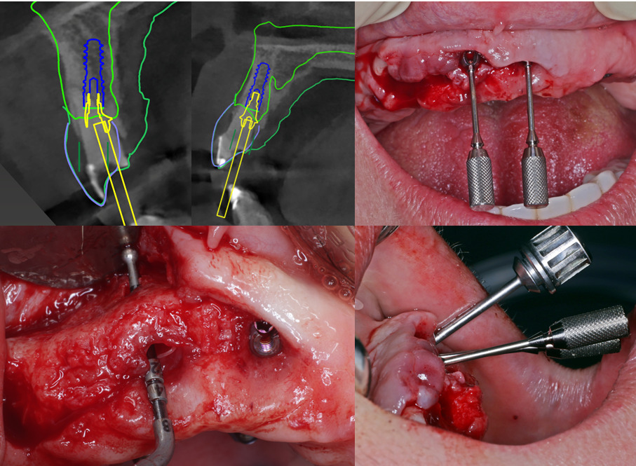
HU values are standardized for CT devices, but in CBCT images the simulated HU values obtained from quantitative gray values suffer from large variability due to numerous reasons, such as a limited field size, high amount of scattered radiation, and the limitations of the reconstruction algorithms (Pauwels et al. 2015). Still, with the high accuracy and reliability for linear bone measurements with a relatively low radiation dose, CBCT is advocated as the imaging tool of choice for 3D dental implant site assessment (Wismeijer et al. 2018). A case demonstrating treatment planning for insertion of an implant to replace an extracted tooth 36 is presented in Figure 3.

Scenarios when CBCT may not be adequate
For some maxillofacial indications, the use of CBCT itself may not be sufficient. For example, the volumetric analysis of the airway for patients with obstructive sleep apnea may require 3D imaging covering the airway from the nasopharynx down to above the clavicles. A typical CBCT device does not accommodate such a large field of view (FOV) and the rotation of the tubehead-receptor assembly may collide with the patient’s shoulders especially if the patient has a larger body size. Moreover, to mimic body posture during sleep, a patient will ideally be scanned in a supine position. This requirement can be met by CBCT devices with a patient bed designed to scan in a supine position.
For various reasons, such as for model surgery, some surgeons may wish to produce a full skull model of the patient by 3D printing technique. The maximum FOV of a typical CBCT device has a diameter of 15–20 cm, which covers the region from the nose tip to the mastoid process or the temporal area only, implying that the parietal region of the skull is not covered.
For endodontic indications such as to visualize a calcified root canal, CBCT should be the first choice for most of us. However, an ex vivo study showed that the presence of gutta-percha reduced the accuracy, sensitivity and specificity of CBCT (but not CT) for detecting vertical root fracture (Khedmat et al. 2012). It implies that CT may theoretically have a role in visualizing small dental structures under certain circumstances, though it is highly unlikely for a dental clinic to have immediate access to a CT during a root canal treatment.
A clinical case using both CBCT and CT
Here, we illustrate the usefulness of both CBCT and CT with a clinical case. A 81-year-old male patient was diagnosed with squamous cell carcinoma in the right mandible. Pre-operative intraoral examination showed pathological change in the buccal cheek and floor of mouth (Figs 4A – B). The right mandible was resected and reconstructed by bone blocks harvested from the fibula, assessed by a pre-operative CT scan (Figs 4C – E). A post-operative CBCT scan was performed to assess the surgical result (Figs 4F – H). This case showed that the treatment of a maxillofacial malignancy may require diagnostic imaging beyond the head and neck region, and that both CBCT and CT scans may be required for comprehensive evaluation and treatment planning.


Conclusions
There are many differences between CT and CBCT imaging. This article discussed some of their differences in terms of the machine, mechanics, and workflow. Based on the latest (6th) ITI Consensus Conference, CBCT is the go-to imaging modality for 3D assessment of dental implant sites. CT, though not designed specifically for dental use as was CBCT, has a role in some maxillofacial and dental cases, but it usually has a higher radiation dose than CBCT and is less readily accessed in our daily practice.
Further reading available on the ITI Academy: